")
")
In this tutorial, we will see the assembly of a RMT-CASE-S2-1LTESE-EUX#B kit to use a 4G modem such as the Quectel EC25-EUX with the Rack Matrix S2 enclosure.
You can buy the kit on our web store : 4G LTE kit for RackMatrix® S2
The S2 enclosure is designed to take in the following motherboards:
- from PC Engines
- APU2,
- APU3,
- APU4
- ou APU6
- from Broachlink
- Noah V1
- Noah V2
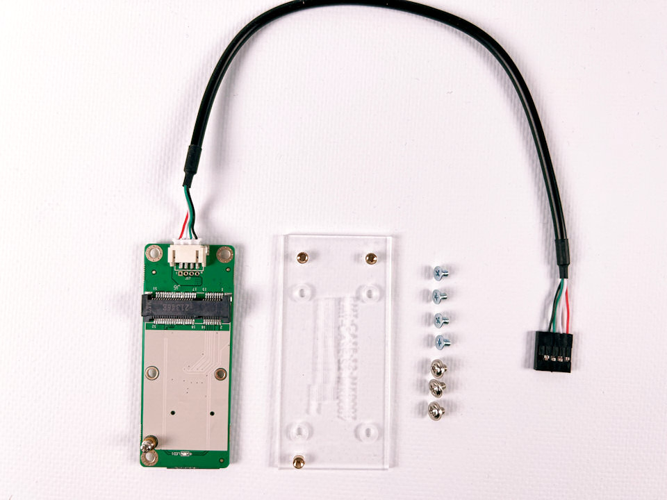
RMT-CASE-S2-1LTESE-EUX#B kit content
Here are the RMT-CASE-S2-1LTESE-EUX#B kit content:
- 4 sunk head screws to fix the PMMA made support to the enclosure
- 3 truss head screws to bind the modem bracket to the PMMA made support
- 1 PMMA made support reference RMT-CASE-S2-MK0007 to screw the modem bracket described below
- 1 modem bracket including a SIM card slot
- 1 internal USB cable
- 1 Quectel EC25-EUX modem
- 2 U.FL / IPEX to SMA female pigtail cables for antennas
- 2 antennes 4G avec connecteur SMA
RMT-CASE-S2-1LTESE-EUX#B kit assembly
Step 1
Assembling is easily done by screwing the PMMA support reference RMT-CASE-S2-MK0007 to the bottom of the enclosure using the 4 sunk head screws.
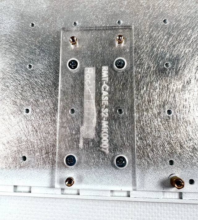
Step 2
Then by screwing the modem bracket to the three inserts.
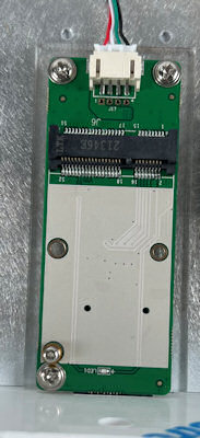
It remains to insert the modem in the mPCIe bracket and clip the two pigtail cables to the U.FL / IPEX connectors on the modem top.
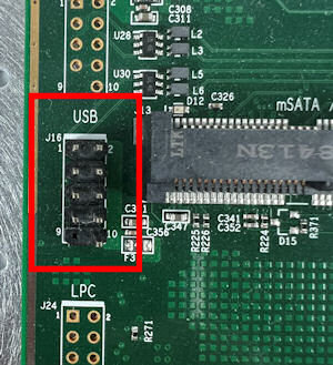
Internal USB Connector Description
The cable connector on the modem side is keyed and can only be inserted one way.
However, connecting the modem bracket to the motherboard requires to use the right header and follow-on the way to plug it.
Here is the pinout of an internal USB connector, allowing to connect up to two devices.
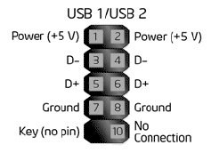
There may be one or two internal USB headers to plug the cable from the modem:
- APU2: 1 header
- APU3: 2 headers. However, avoid using the J13 connector on the APU3A
- APU4: 2 headers on APU4C and later, 1 header only on APU4B
- APU6: 2 headers
- Noah V2 : 1 header
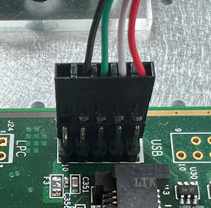
Step 4
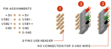
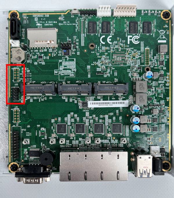
Here is how to connect the 4-pin cable coming from the modem bracket on an APUx board:
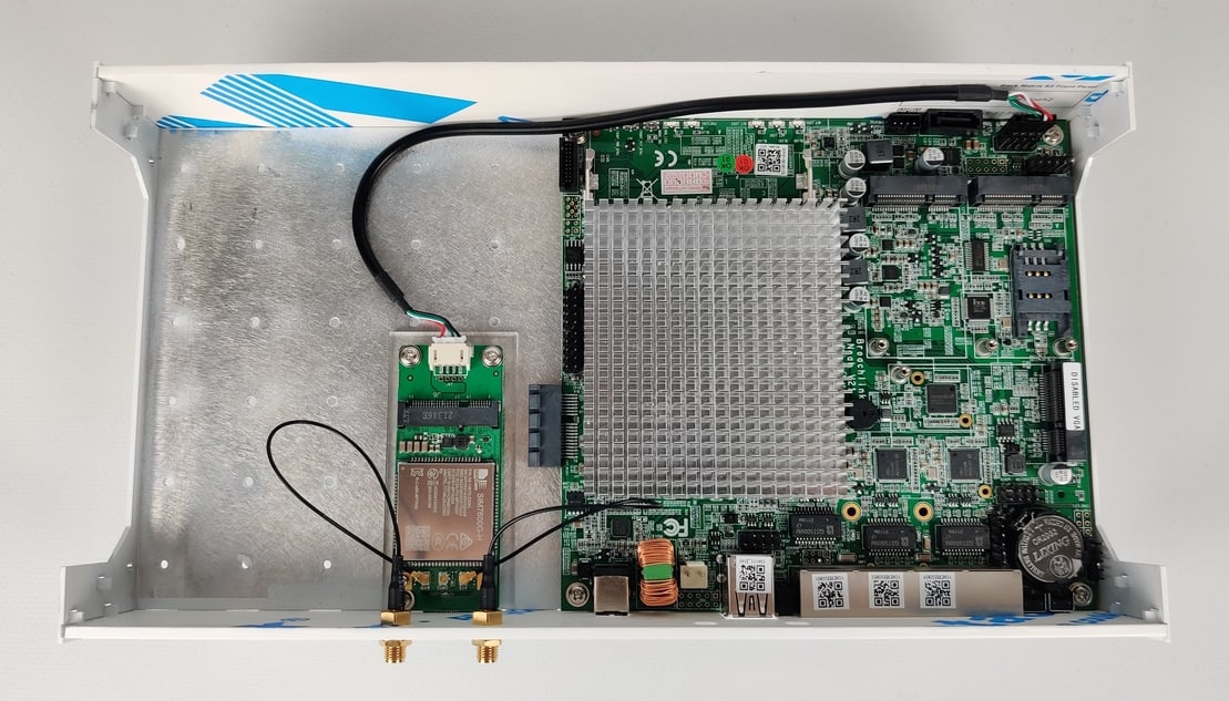
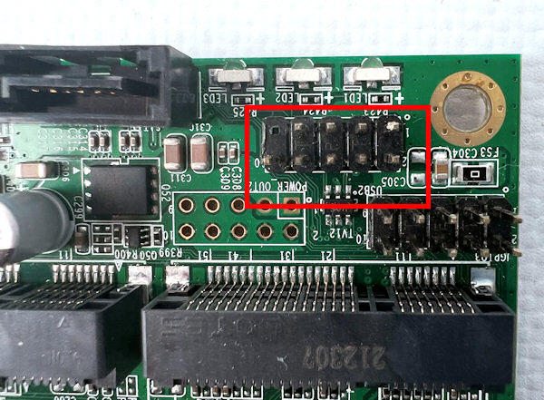
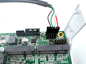
And here is how to plug a Noah v2 board, between the unpopulated POWER_OUT2 connector and the 3 LED:
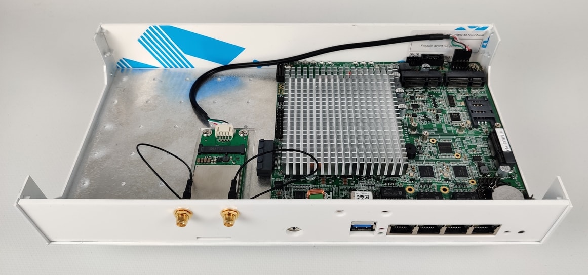
End result
You have reached the end of the installation instructions and your 4G modem is hopefully ready for service: